March 8th Ruling the unruly
Wherein the segment revolt is described and efforts to quell described
As I sit in front of my computer working on the segment images, I enjoy the fact that by being a measurer of length, I am a ruler. A kingdom of millimeters but a kingdom all the same.
This week’s experiment was free of face palms, glitchy computers, and foggy oculars: A smooth run from start to end. And as such brought me face to face with variation. Unruly segment lengths. Restive subjects.
Here are this week’s numbers:
——————————– Elongation rate Widening rate
____________________ % / hr % / hr
3 µM auxin + Water 6.1 1.0
3 µM auxin + 1o mM KCl 4.2 -0.5
3 µM auxin + 20 mM KCl 4.7 -0.2
3 µM auxin + 40 mM KCl 4.0 0.2
3 µM auxin + 80 mM KCl 5.0 0.1
As a ruler, I am not amused. Were I a tyrant, I would hurl these segments in the dungeon. But being more kindly disposed, I seek to learn what troubles my subjects thus. Clearly, they are troubled, and noisy. This time, the baseline treatment (auxin in water) elongated at 6% per hour whereas last week it was around 5%. Conversely, last time the auxin in KCL nearly hit 6% per hour, whereas this time they were down between 4 to 5 % per hour. Furthermore, this time, there was no trend based on the increasing concentration of KCl; the numbers just flounce.
While there is always noise in experiments, here the size of the noise, around 1% per hour, represents a decent sized chunk of the size of the signal for elongation (about a quarter to a fifth) and is equal to the signal for widening. The obvious conclusion is that something must be done.
Where could the noise be coming from?
Biology is an obvious source of trouble. I noticed that I am cutting the segments irregularly, in that many of them have oblique ends, rather than straight. The oblique ends might enhance wounding but definitely make measuring more difficult. I am going to modify my cutting stroke. I have been using my finger to push the mesocotyl down onto a pair of razor blades, held in a block and facing up. Sounds scary but I haven’t cut myself. I do this three times to get three segments per mesocotyl. But sometimes one end of the mesocotyl goes down before the other, making an oblique cut. The jig is large enough to hold two more blades and I can use a glass slide to press down on the mesocotyl. I think this will provide more uniform cuts.
And there is room in the washer dish for more segments. I can use nine instead of six. This will take more time to set up and more material but seems warranted to rule the plants.
While biology is everyone’s error scapegoat, one should also throw a few stones at physical errors. It struck me that there might be geometrical distortion in the lens. This is a common defect, where magnification at the edges of the field is a little bit higher or lower than in the center. It is easy to spot this because the afflicted lens will convert an image of a grid into something with curves, either inward (a “pincushion”) or outward (a “barrel”) depending on whether the center magnification is bigger or smaller than that of the edges.
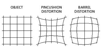
Common lens distortions. See http://robocup.mi.fu-berlin.de/buch/chap9/ComputerVision.htm
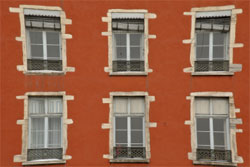
Example of pincushion distortion or sloppy builders. Taken from here.
Not having any transparent graph paper handy, I fashioned a splinter of wood, about the same size as the segments, and imaged it at different places of the field of view, from edge to center. Lo and behold! There is about a 3% difference in length from center to edge.
B’gorrah! Throw that lens in the dungeon. I am sorely tempted. The distortion is grievous, large enough to wreck havoc with my ruling because the segments are free to move from center to edge over the four hours between initial and final photo. But alas, as in the manner of these things, punishment won’t solve the problem. I need a cure.
One possibility is to close down the iris. I have been imaging with the iris quite wide open to increase the numerical aperture of the lens and hence its resolving power. I am not sure but I think that by stopping down the iris and making the light rays all go through the center of the lens, the distortion will lessen. This will come at a resolution cost but one that should amount to substantially less error than that caused by the barrel distortion. At least, I can check by taking a repeat set of measurements with another segment-sized splinter, this time with the iris quite closed.
Another possibility is correction by computation. This takes advantage of the fact that the lens distortion is a permanent feature of the lens. Thus, if I measure the distortion at each point in the field, I can generate a correction factor or each point in the field, and apply that to un-distort the image. Mathematical optics. I can do this by finding a transparent grid somewhere and imaging it. Because the lines of the grid can be taken as straight, their curvature in the image gives rise to the corrections. This too won’t be perfect, there will be a bit of a mathematical fudge, that probably amounts to a pixel or so. It will be interesting to see which approach, stopping down the iris versus the mathematical correction wins out. Stay tuned!